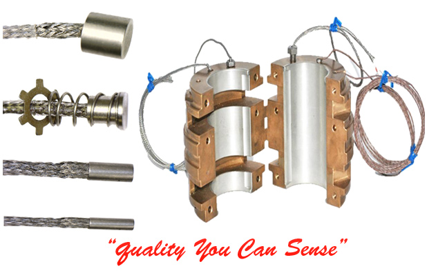
Comparison of Thermocouples
Measuring temperature electricallyElectrical temperature measurement is found in a wide variety of industries. From melting steel to baking cookies, the range of temperatures can vary greatly and the type of sensor required to measure these temperatures must be chosen accordingly.
Thermocouples
A thermocouple is a temperature-sensing element which converts thermal energy directly into electrical energy. In its basic form it consists of two dissimilar metallic conductors connected in a closed loop. Each junction forms a thermocouple. If one thermocouple is maintained at a temperature different from that of the other, an electrical voltage proportional to this temperature difference will be produced by the circuit. Thermocouples are interchangeable, cheap, have standard connectors, and can measure a wide range of temperatures. The main limitation of thermocouples is their accuracy; system errors of less than 1 °C can be difficult to achieve.
The thermoelectric effect (Seebeck effect)
In 1822, physicist Thomas Johann Seebeck accidentally discovered that when any conductor is subjected to a thermal gradient, it will generate a voltage. Any attempt to measure this voltage involves connecting another conductor to the "hot" end. This additional conductor will then also experience the temperature gradient, and develop a voltage of its own which will oppose the original; the magnitude of this effect depends upon the metal in use. If there is the same temperature at the two junctions there is no flow of current since the partial voltages produced at the two points cancel each other. Using a dissimilar metal to complete the circuit will have a different voltage generated, leaving a small difference voltage available for measurement, which increases with temperature. This difference can typically be between 1 to 70 µV/C? for the available range of metal combinations. Certain combinations have become popular as industry standards, driven by cost, availability, convenience, melting point, chemical properties, stability, and output.
Connecting a thermocouple
When choosing a thermocouple, consideration should be given to the insulation, thermocouple type, and probe construction.
RTD's Resistance Temperature Detectors (RTDs), also referred to as platinum resistance thermometers (PRTs) or resistance thermometers, are temperature sensors that change resistance at a predetermined rate in response to variation in temperatures. RTD's are rapidly replacing thermocouples in many industrial applications below 600? C due to their higher sensitivity and accuracy over thermocouples.
RTDs types
- Film thermometers Film thermometers have a thin layer of platinum (as thin as 1 micrometer) on a substrate. Advantages of this type of RTD are relatively low cost and fast response. Such devices have improved in performance although the different expansion rates of the substrate and platinum give "strain gauge" effects and stability problems.
- Wire-wound thermometers Have greater accuracy, especially for wide temperature ranges. The coil diameter provides a compromise between mechanical stability and allowing expansion of the wire to minimize strain and consequential drift.
How do RTD's work? Resistance thermometers offer greater stability, accuracy and in some cases repeatability than thermocouples. While thermocouples use the thermoelectric effect to generate a voltage, RTD's require a power source to operate and use electrical resistance. Ideally, the resistance will vary linearly with temperature. Resistance thermocouples are most often made using platinum, due to its linear resistance-temperature relationship as well as its chemical inertness. The platinum detecting wire needs to be guarded from contamination to remain stable. Commercial platinum grades are produced which exhibit a change of resistance of 0.385 ohms/°C (European Fundamental Interval) The sensor is usually made to have a resistance of 100 ? at 0 °C.
Resistance thermometers require a small current to be passed through in order to determine the resistance. This can cause self-heating so it is important to minimize the current to reduce self-heating errors. Care should also be taken to avoid any strains on the resistance thermometer in its application. Lead wire resistance should be considered, and adopting three and four wire connections can eliminate connection lead resistance effects from measurements.
RTD wiring Configurations
- Two-wire configuration The simplest resistance thermometer configuration uses two wires. It is only used when high accuracy is not required as the resistance of the connecting wires is always included with that of the sensor, thus leading to errors in the signal. This applies equally to balanced bridge and fixed bridge systems. The values of the lead resistance can only be determined in a separate measurement without the resistance thermometer sensor and therefore a continuous correction during the temperature measurement is not possible.
- Four-wire configuration The four wire resistance thermometer configuration even further increases the accuracy and reliability of the resistance being measured. A standard two terminal RTD is used with another pair of wires. One pair carries the excitation current while the other pair carries the reulting RTD voltage back to the measurement system. No current flows in the second pair, so lead resistnace has no effect on accuracy.
Thermistors are a type of resistor with an electrical resistance that possesses either a negative or positive temperature coefficient of resistivity. Thermistors are composed of solid semiconducting materials with a resistance that decreases 4% per °C. They are constructed in a variety of sizes and may be obtained with thermal time constants of a millisecond or less. Thermistors produce a non-linear voltage and because of this are limited to a useful temperature span of only about 100°C. Thermistors are the most accurate of the temperature sensors, ~±0.02 °C, as well as the most sensitive. Their response time is short in relation to RTD's, and about the same as thermocouples.
Connecting a Thermistor The resistance of thermistors is normally several orders of magnitude greater than any lead resistance. The lead resistance therefore, has a negligible effect on the temperature reading and thermistors are almost always connected in a 2-wire configuration.
|
