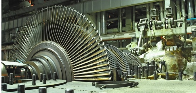
RTD Bearing Sensor
The bearings of industrial rotating equipment operate under arduous conditions – often for considerable periods of time. The most reliable indicator of bearing condition is the temperature of the metal beneath the shoe. Recognition of rising temperature can provide a warning of the breakdown of the lubricating oil film, allowing machine shutdown and maintenance to take place before catastrophic failure of the bearing and possible damage to its mounting. Conax Miniature Bearing Sensors provide a simple and cost-effective method to monitor bearing temperatures.
FEATURES
-
• For embedded applications in rotating machines
-
• RTDs – 100Ω platinum, 0.00385 Ω/Ω/°C
-
• Various styles and sizes
-
• Operating Temperature: to +250° F (+120° C)
-
• Thermocouple assemblies also available – consult factory
SPECIFICATIONS
RTDs: 100Ω platinum, 0.00385 Ω/Ω/°C; 2-, 3- and 4-wire single
element configurations, Class 'B' tolerance to DIN 43760:1980 and
IEC 751:1995
Silver plated, stranded copper conductors, 24 AWG, Teflon® insulated
with extruded Teflon jacket overall or 24 or 26 AWG, Teflon insulated
with optional stainless steel braid and extruded Teflon jacket overall.
Sheath Materials: 316SST, Copper Alloy or Brass. Resistance Temperature Detectors also known as RTDs, accurately sense temperature with an excellent degree of repeatability and interchangeability of elements. RTD stands for Resistance Temperature Detector. RTDs are sometimes referred to generally as resistance thermometers. The RTD is composed of certain metallic elements whose change in resistance is a function of temperature. In operation, a small excitation current is passed across the element, and the voltage, which is proportional to resistance, is then measured and converted to units of temperature calibration. The RTD element is manufactured by winding a wire (wire wound elements) or plating a film (thin film elements) on a ceramic or glass core and sealing the element within a ceramic or glass capsule.
Since the majority of RTDs have low initial resistance, often 100 ohms, and have a small change in resistance per unit of temperature range, the resistance of the lead wire is often compensated for with a three or four wire bridge configuration built into the measuring devices. By selecting the proper elements and protective sheathing, RTDs can operate in a temperature range of (-200 to 650) C [-328 to 1202] F.
Thermometrics manufactures RTDs for a variety of industry applications. From single- or dual-element RTDs, to PT100's to Sanitary CIP types, Thermometrics has the right sensor for your job. If what you need is not available from our company catalog, our product engineers and sales staff will design an RTD for your specific application, including temperature sensor assemblies that require connection heads, thermowells and/or transmitters.
What is an RTD Element?
Element is the component, which actually does the measuring. Based on the function it is going to perform and the technology employed in fabricating it, an element can have coils and/or different patterns to provide a signal, which then is used to measure the changes in different properties of energy.
The Advantages of RTDs
The advantages of RTDs include stable output for long period of time, ease of recalibration and accurate readings over relatively narrow temperature spans. Their disadvantages, compared to the thermocouples, are: smaller overall temperature range, higher initial cost and less rugged in high vibration environments. They are active devices requiring an electrical current to produce a voltage drop across the sensor that can be then measured by a calibrated read-out device.
Selecting an RTD
RTD Element Types
When deciding the RTD element type, first consider what instrument you will be reading the sensor with. Choose an element type that is compatible with the instrument’s sensor input. By far the most common RTDs are 100 Ohm Platinum with .00385 temperature coefficient. Type PB is an example
|
Type |
Element Material |
Base Resistance (Ohms) |
TCR (Ohm/Ohm/C) |
Base Resistance Tolerance +/- |
TCR Tolerance % |
|
CB |
COPPER |
10 OHMS AT 25C |
.00427 |
0.2% |
1% |
|
CC |
COPPER |
10 OHMS AT 25C |
.00427 |
0.5% |
1% |
|
NA |
NICKEL |
120 OHMS AT 0C |
.00672 |
0.5% |
1% |
|
PA |
PLATINUM |
100 OHMS AT 0C |
.00385 |
0.06% |
0.12% |
|
PB |
PLATINUM |
100 OHMS AT 0C |
.00385 |
0.12% |
0.35% |
|
PC |
PLATINUM |
100 OHMS AT 0C |
.00385 |
0.5% |
1% |
|
PE |
PLATINUM |
100 OHMS AT 0C |
.00391 |
0.12% |
0.35% |
|
PF |
PLATINUM |
100 OHMS AT 0C |
.00391 |
0.5% |
1% |
|
PG |
PLATINUM |
100 OHMS AT 0C |
.00375 |
0.12% |
0.35% |
|
PH |
PLATINUM |
100 OHMS AT 0C |
.00392 |
0.5% |
0.1% |
Accuracy
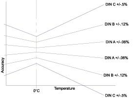
Secondly, decide what accuracy is needed in your measurement. Accuracy is a combination of both base resistance tolerance (resistance tolerance at the calibration temperature) and temperature coefficient of resistance tolerance (tolerance in the characteristic slope). Any temperature above or below this temperature will have a wider tolerance band or less accuracy (see graph below). The most common calibration temperature is 0°C.
Leadwire Effects
Measurement of temperature with a resistance temperature detector is a matter of measuring resistance. Unbalanced Wheatstone bridges are invariably used to measure the resistance. When measuring the resistance of the sensing element, all external factors must be minimized or compensated for, in order to obtain an accurate reading.
A major cause of error can be the resistance of the leadwires, especially in two lead configurations.
The resistance is in series with the sensing element, so the readout is the sum of the resistances of the sensing element and the leadwires. Two-lead RTD’s are possible when the sensing element has a high resistance and the leadwires have a low resistance.
When the leadwire resistance is comparably high, however, it must be compensated. Compensation can be achieved with a three-lead configuration. As shown in the three-lead diagram, one side of the power supply is taken to one side of the RTD via L3. This puts L1 and L2 in opposite arms of the bridge so they cancel each other out and have no effect on the bridge output voltage.
Three-lead connections are recommended for RTDs, especially with low sensing element resistance, where a small leadwire resistance can have a large effect on readout accuracy.
RTD INSTALLATION & MAINTENANCE
General
An RTD is a sensor whose resistance changes as its temperature changes. The resistance increases as the temperature of the sensor increases. The resistance vs temperature relationship is well known and is repeatable over time. An RTD is a passive device. It does not produce an output on its own. External electronic devices are used to measure the resistance of the sensor by passing a small electrical current through the sensor to generate a voltage.
Standard Tolerances
RTDs are built to several standardized curves and tolerances. The most common standardized curve is the ‘DIN’ curve. The curve describes the resistance vs. temperature characteristics of a Platinum, 100 ohm sensor, the standardized tolerances, and the measurable temperature range. The DIN standard specifies a base resistance of 100 ohms at 0ºC, and a temperature coefficient of .0038500 ohms/ohms/ºC. The nominal output of a DIN RTD sensor is shown below:
There are two standard tolerance classes for DIN RTDs. These tolerances are defined as follows:
|
DIN Class A |
Temperature tolerances: |
+/-(0.15 + .002|T|°C) |
|
DIN Class B |
Temperature tolerances: |
+/-(0.3 + .005|T|°C) |
|
DIN Class C |
Temperature tolerances: |
+/-(1.2 + .005|T|°C) |
Sensor Connections
RTD Sensors are available in a number of different leadwire configurations. The most common configuration is the single element, three lead configuration. Schematics of the available leadwire configurations are shown below:
Two wire sensors are typically used in applications where accuracy is not critical. The two wire configuration allows for the simplest measurement technique, but suffers from an inherent inaccuracy due to the resistance of the sensor leads. In the two wire configuration, there is no way to directly compensate for the resistance of the leadwires which will cause an offset increase in the resistance measurement.
Three wire sensors are built with a compensation loop to allow the measurement to factor out the resistance of the leads. With this configuration, the controller/measurement device makes two measurements. The first measurement measures the total resistance of the sensor and the connecting leadwires. The second measurement is the resistance of the compensation loop resistance. By subtracting the compensation loop resistance from the total resistance, an account net resistance is determined. Three wire sensors are the most common and give a good combination of accuracy and convenience.
The four wire sensor configuration and measurement techniques allow measurement of the sensor resistance without the influence of the leadwires. While this technique gives the best accuracy, many industrial controllers/measurement devices cannot make a true four wire measurement.
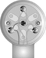
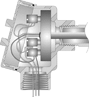
The transition from the sensor leadwires to the field wiring is typically done in a connection head attached to the sensor. Terminal blocks are used to facilitate the connection. A typical terminal block/sensor connection is shown in the following figure.
Mechanical connection
RTD sensor assemblies typically use pipe threads (NPT) for the mechanical connections between the connection heads, extensions and thermowells. For proper operation you should tighten the threads at least 1-2 turns past hand tight. This will ensure that the threads mate tightly, and that the proper sensor assembly length is obtained. To prevent thread galling RTD Company recommends that anti-sieze compound or Teflon plumbing tape is used on all NPT threads.
Ensuring accurate performance
To ensure good performance of the sensor, the sensor must be in good thermal contact with the process. When using a sensor in conjunction with a thermowell you should use a suitable heat transfer compound to fill the air space between the sensor and the bore of the thermowell. This will improve the heat transfer between the process and the sensor, reducing the stem conduction error and improving the response time of the sensor. For moderate temperature applications (less than 250ºC) a silicone based heat transfer compound should be used. Higher temperature applications will require a graphite based material. An easy way to apply the heat transfer compound is to apply a generous amount to the tip of the sensor and insert the sensor into the thermowell, pressing the sensor firmly into the well until the tip reaches the bottom of the thermowell bore. The RTD sensor should be isolated from the sensor sheath and other metal components. Checking the insulation resistance of the sensor is an easy test to ensure the integrity of the sensor. Measure the resistance between the sensor leads, and the metal sheath of the sensor. The resistance should measure at least 100 megohms (100,000,000 ohms). Lower insulation resistances could be an indication that the sensor has suffered damage.
RTD Temperature vs. Resistance Table
Accuracy Standards
RTD Signals
RTD Theory and Standards
Coil Resistor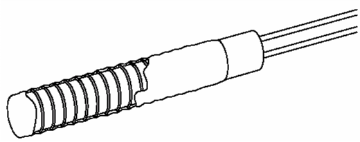

Wire Wound Resistor
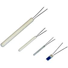
What are the main differences between thin-film element and wire-wound element?
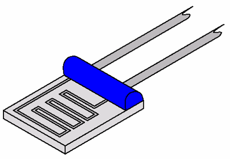
Thin film element is manufactured by using highly sophisticated technology called photolithography. This technology enables sensing element to be more rugged, smaller in size, more accurate, and more cost affective then traditional wire-wound elements. Since wire-wound elements are labor intensive, they tend to be more expensive
Thin Film RTD
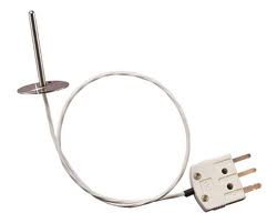
Sanitary Finish RTD
| 