Useful Info
Cidunt ut laoreet ater dolore atre magna aliquam inim atere hasel veniam, quis nostrud porta qmet queryten msiole aters.


3 Wire RTD
Why Use a 3 Wire RTD?
The three wire configuration provides a compensation loop that can be used to subtract the lead wire resistance from the resistance measurement of the element loop, resulting in a value for just the element resistance. As will be shown, achieving an accurate measurement with this method is predicated on the resistance of each of the leads being exactly equal. Unfortunately this is seldomthe case, and steps must be taken in the design and application of a three wire sensor to maintain the accuracy of the measurement.
In order to minimize the effects of the line resistances and their fluctuation with temperature it is usual practice to employ a three-wire circuit. It consists of running an additional wire to one contact of the RTD. This results in two measuring circuits of which one is used as reference. The 3-wire circuit makes it possible to compensate for the line resistance both in its amount and also in its temperature variation. It is however a requirement that all three conductors have identical properties and are exposed to identical temperatures. This usually applies to a sufficientdegree so that the 3-wire circuit is the most widely used method today. No line balancing is required.
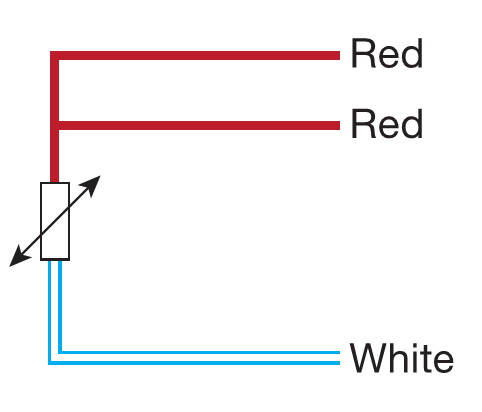
3 Wire RTD Color Code
Lead wire colors are defined in the IEC 60751-2008 standard where all wire colors are shown as in the following figure.
3 Wire RTD Wiring Diagram
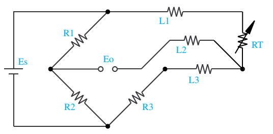
In this circuit there are three leads coming from the RTD instead of two. L1 and L3 carry the measuring current while L2 acts only as a potential lead. No current flows through it while the bridge is in balance.Since L1 and L3 are in separate arms of the bridge,resistance is canceled. This circuit assumes high impedance at Eo and close matching of resistance between wires L2 and L3.